Evaporator Like the condensing unit evaporator coils also have performance curves Figure 2. 1 A staggered pattern is more.

Pdf Design Of Evaporator Cooling Coil For Cooling Load
Our proprietary circuiting provides for optimal.
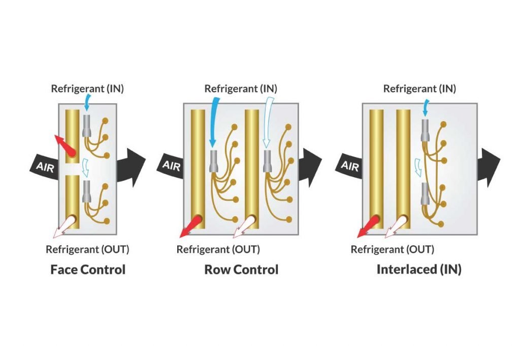
. The selection process of the evaporators that operate in a system of refrigeration with CO2 is very similar to. Unique interlaced circuiting options assure uniform refrigerant distribution. Single dual or quad compressor circuits allow precise capacity control.
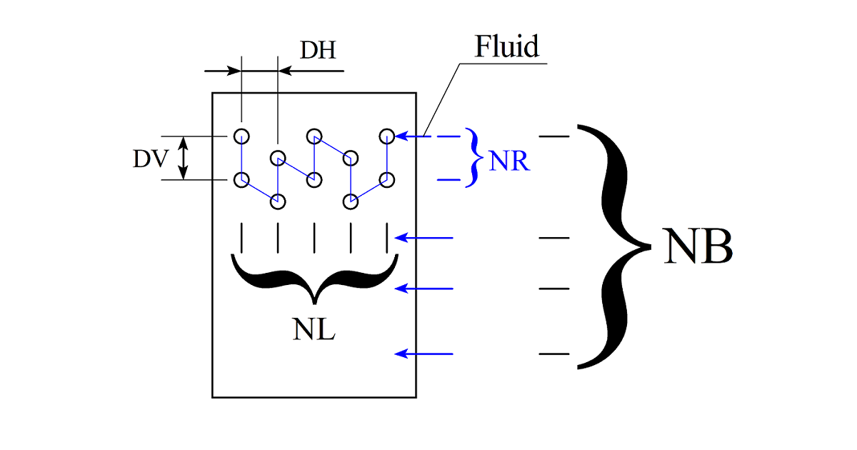
Knowledge there is not an existing distributed simulation model for the study of tube circuitry of evaporator coils. E Coil Type N Circuiting 14 Fins Per Inch 06 Rows Deep C Fin Design 2400 Fin Height in 14400 Finned Length in 5 E N 14 06 C 2400 x 14400 Tube Outside Diameter 3 0375. Bruce Nelson President Colmac Coil.
Coil on 134a with a circuit load of 3 kW and finned. RowsNL along air flow. Focuses on Methods to design the cooling and dehumidifying coil or Direct Expansion evaporator coil.
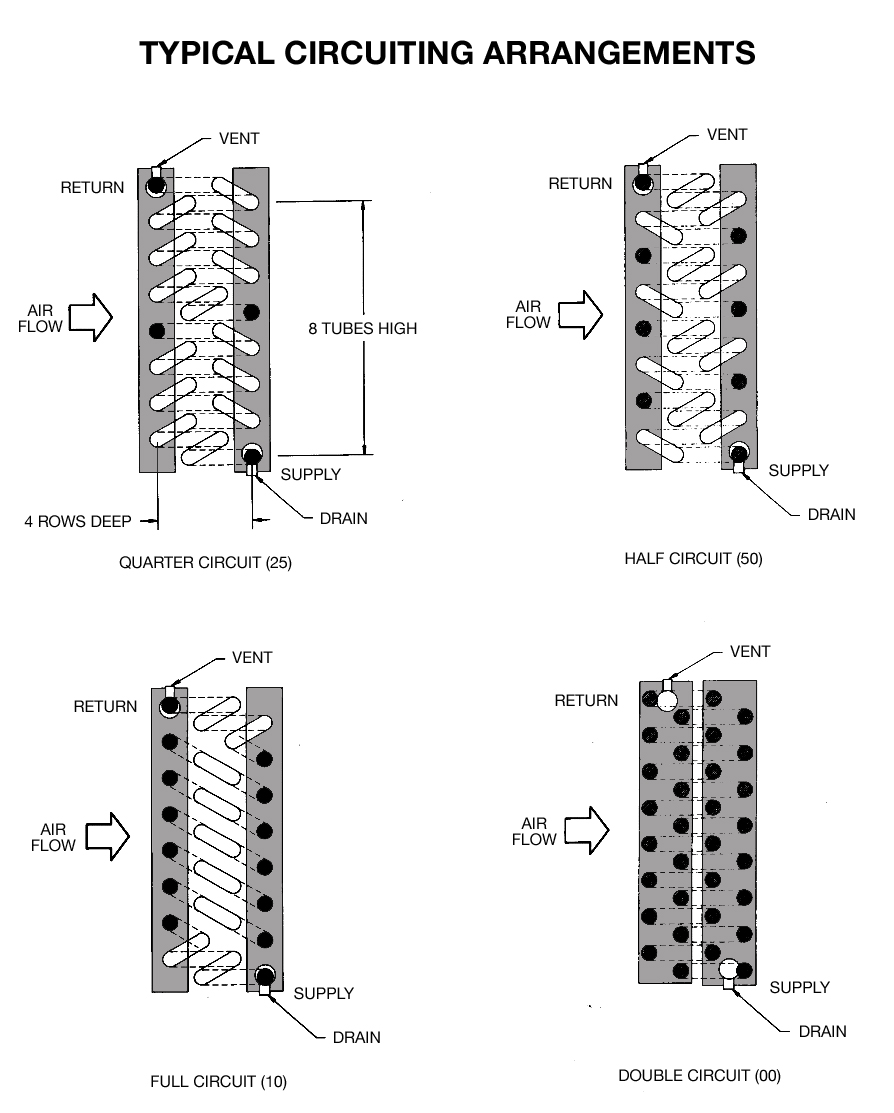
28 5EJ Evaporator Coils 3 through 10 Rows 12ʺ to 54ʺ FH. Direct-expansion evaporator coils are used in low temperature refrigeration applications to cool and sometimes dehumidify air. Evaporator Coil Circuiting Options.
Cellar contractors have asked for a design that does not take away from the racking capacity and is virtually invisible in the cellar. 5EF Evaporator Coils 2 through 12 Rows 12ʺ to 54ʺ. In the design of evaporator coils increasing refrigerant mass velocity can.
Methods to design the cooling and dehumidifying coil either chilled water coil or Dx evaporator coil are usually based on log mean enthalpy or log equivalent dry-bulb temperature difference. Design of Evaporator with CO2 Coolant. Ad Custom HVAC Coil for Your Business.
The Product Evaporator circuit consists of an insulated pipe an evaporator valves a single wall pipe and sensors. Designed for use in comfort cooling process cooling and refrigeration Madok evaporator coils are proven for use with todays refrigerants. We have created a ceiling mount split system evaporator.
See Figure 1 - Evaporator Coils 5 E N 14 06 C 2400 x 14400 5 Tube Outside Diameter 3 0375 4 0500 5 0625 E Coil Type E Evaporator N Standard Circuit Ratio Q 14 serp H. An evaporator or direct expansion DX coil works on the refrigeration effect. In a coil copper tubes are arranged parallel to one another either in staggered pattern or non-staggered pattern along the length L of the coil.
Initial evaporator widthLD mm. Pounders Marine Diesel Engines and Gas. Cooling occurs when a fluid under pressure and at a temperature.
All evaporator coils are counter flow circuited and equipped with pressure type distributors and all distributor tubes are of equal length to assure equal distribution of refrigerant to each. 29 5EK Evaporator Coils 4 and 8 Row 15ʺ to 54ʺ FH 30 5EN. Which are usually based on log mean enthalpy or log equivalent dry-bulb temperature.
Air passing across the fins is cooled as the. REFRIGERANT EVAPORATOR DX COIL. Coil arrangement 0In-line 1Cross.
One obvious advantage or reason that you might split a DX coil is that you can shut down 1 of the compressors when the cooling load does not require it. Ad Custom HVAC Coil for Your Business. Use the corrected circuit load in the selection tables and use the tube diameter nearest to the required duty.
This in turn saves. Ambient design is 95F then the SST of the condensing unit must be 45F. Designed for use in comfort cooling process cooling and refrigeration Coilmaster evaporator coils are proven for use with all of todays refrigerants.
2

Numerical And Experimental Studies Of Refrigerant Circuitry Of Evaporator Coils Sciencedirect
Understanding Coil Circuiting With A Simple Guide Campbell Sevey
Air Second Side Evaporator Design Calculation
The Benefits Of Intertwined Circuiting In Split Coils Fabtech
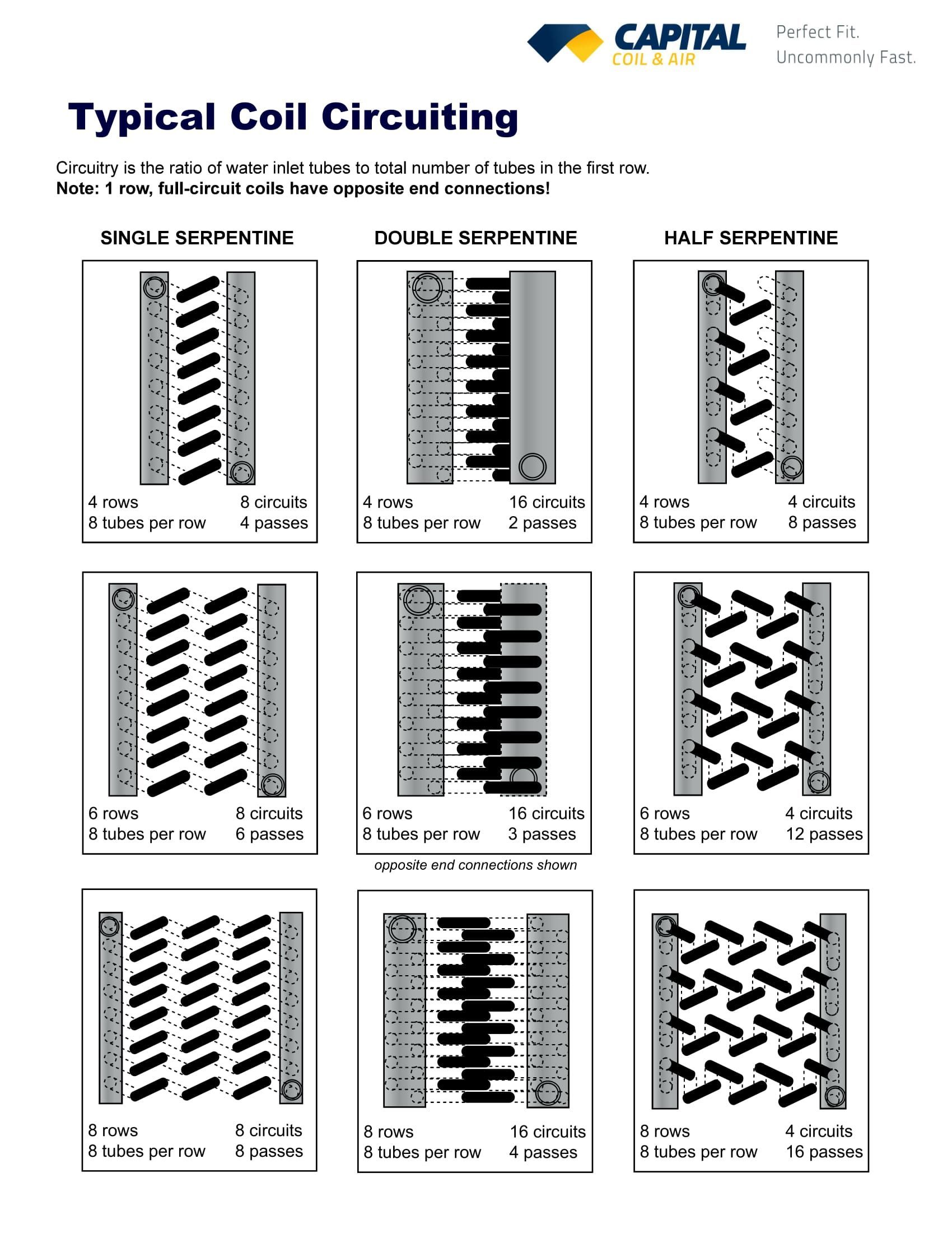
Chilled Water Cooling Coils Circuiting Made Easy
Chilled Water Cooling Coils Circuiting Made Easy

Coilmaster
0 comments
Post a Comment